Pilot Left Panel
Co-Pilot/Gunner Left Panel
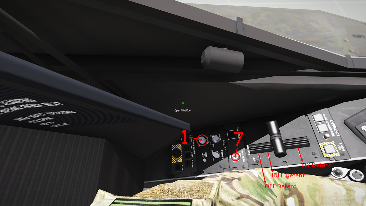
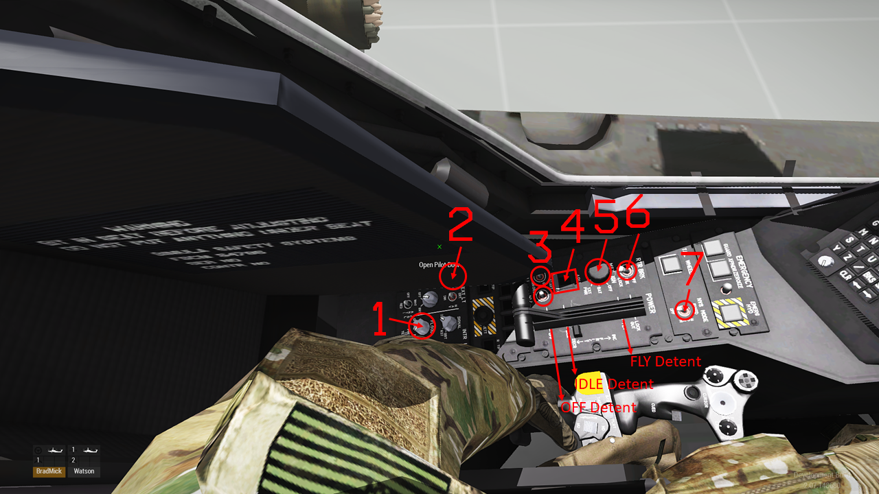
Left Panel Description
- FS/BS Flood Light Knob - This control toggles the crewstation floodlighting and panel lighting ON/OFF.
- FS/BS Exterior Light Switch - This control toggles the aircraft exterior lighting.
- BS Engine 1 and 2 Start Switches - Toggle the engine starter ON/OFF. To start the engines, Battery and Auxilliary Power Unit (APU) power are required and the Rotor Brake must be OFF.
- BS Auxilliary Power Unit (APU) Pushbutton - Toggles the APU ON/OFF. When ON the pushbutton will be illuminated, when OFF the pushbutton will be dark.
- BS Master Ignition Switch - Toggles the aircraft battery ON/OFF.
- BS Rotor Brake Switch - Toggles the Rotor Brake switch from OFF to Brake (BRK). By default it is set to OFF.
- FS/BS NVS Mode Switch - Toggles the Helmet Display Unit (HDU) Forward Looking Infrared (FLIR) video ON/OFF for night flight.
Additionally, there are three detents for the Engine 1/2 Power Levers: OFF, IDLE and FLY. Clicking within each zone will advance/retard the Power Levers automatically.
Pilot Front Panel
Co-Pilot Gunner Front Panel
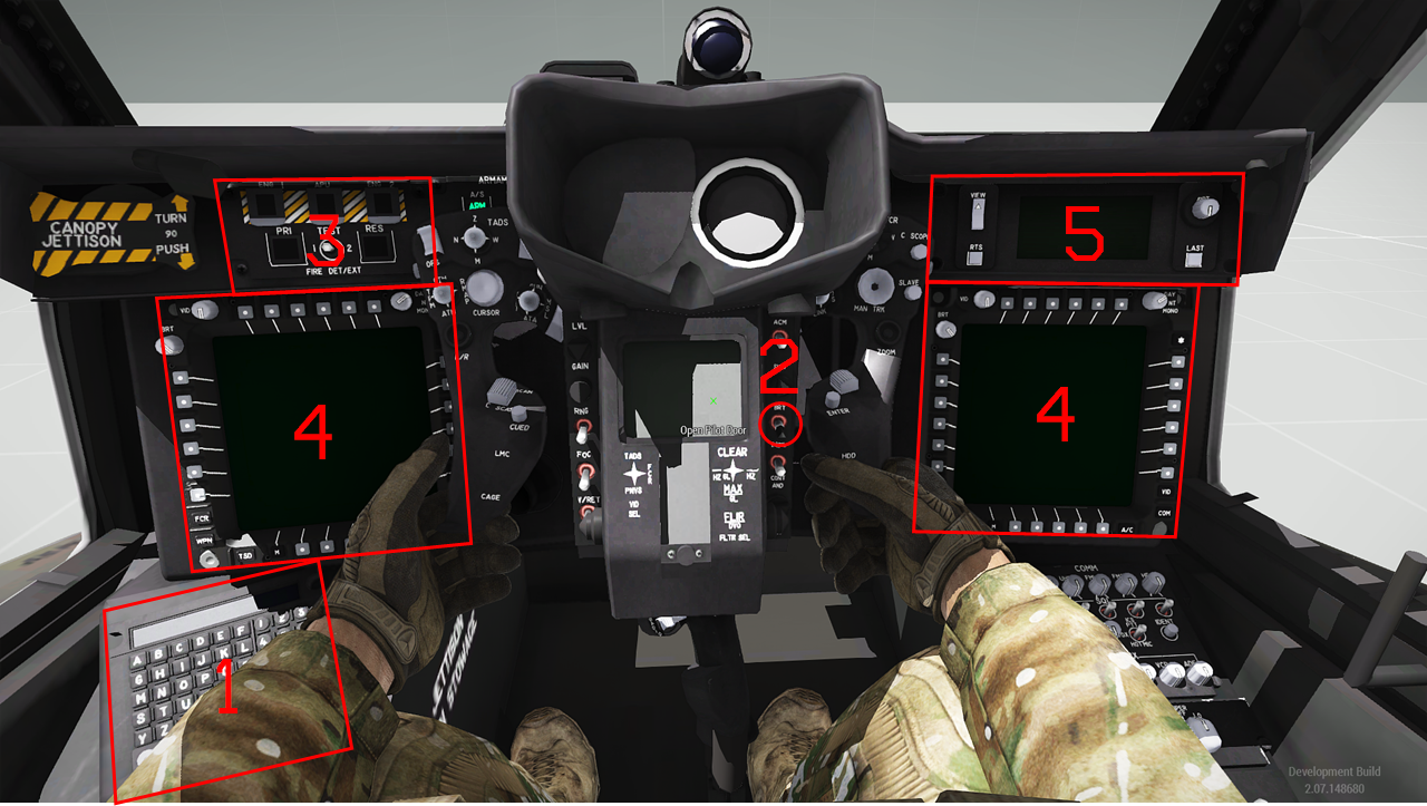
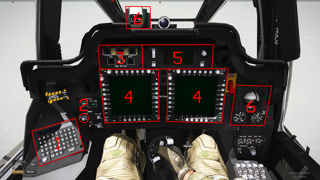
Front Panel Description
- Keyboard Unit (KU) - The KU is used to input data into the aircraft and can also be used as a calculator.
- IHADSS Brightness Knob/Switch - NO LONGER IMPLEMENTED This control toggles the HDU symbology ON/OFF.
- Fired Detection/Extinguishing Panel
- The TEST switch allows the crew to test that the system is functioning properly.
- When a fire is detected, the associated ENG 1/2 or APU FIRE lights will illuminate. Pressing the illuminated button will ARM the system and cut fuel to that engine thus shutting it down and cause the DISCHARGE lights to illuminate. Pressing the PRI (Primary) or RES (Reserve) buttons will discharge that bottles fire extinguishing agent. The bottles can be recharged by repairing the aircraft.
- Multi-Purpose Displays (MPD) - The left and right MPD’s feature 24 Variable Action Buttons (VABs) and 6 Fixed Action Buttons (FABs) around the display. The VABs are grey in color and are numbered 1 to 6 from left to right and top to bottom. When referencing a specific VAB, it’s position around the MPD (Top/Bottom, Left/Right) and number are used, i.e. T1, B4, R3, etc. The FAB include: FCR, WPN, TSD, A/C, COM and VID. The Menu (M) button, while a FAB, it is counted as B1.
- Up-Front Display (UFD) - The UFD provides the crews with active Warnings (W), Cautions (C) and Advisories (A) as well as currently selected frequencies. In the bottom left corner of the UFD is the current fuel amount in pounds. The bottom right corner provides the crew with a clock.
- Pilot Standby Instruments - Provide the pilot with the ability to continue flying the aircraft in the event of a complete electrical failure or loss of both MPDs as a result of other damage. Includes the magnetic compass, standby attitude indicator, airspeed indicator and altimeter.
Pilot Right Panel
Co-Pilot Gunner Right Panel
Right Panel Description
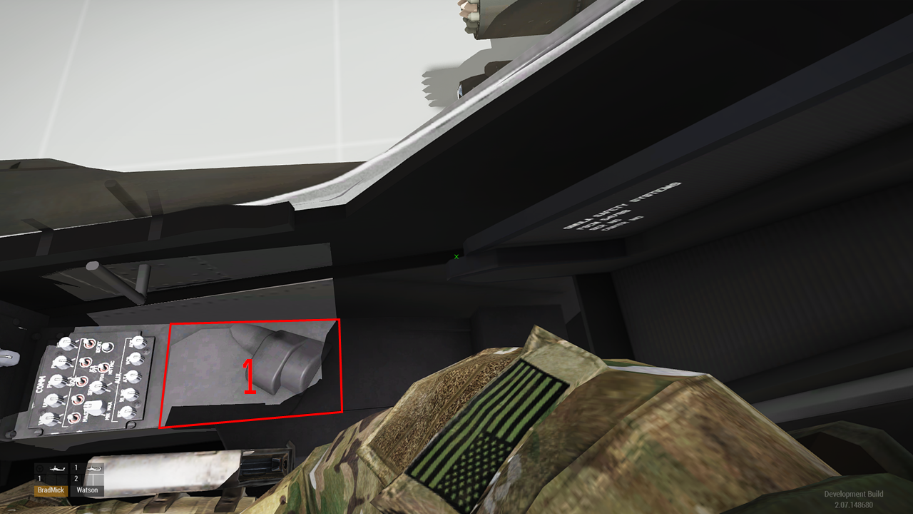
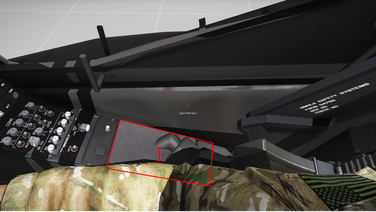
- HDU Storage - Clicking here will ‘attach’ the Helmet Display Unit (HDU) to the helmet. Once attached and on battery power, each crewmember must click their individual IHADSS Brightness Knob/Switch in order to display symbology.