ADD FLT PAGE IMAGE HERE
Introduction
The FLT page displays the attitude indicator, waypoint information, barometric altimeter, radar altimeter and radar height tape when applied, vertical situation indicator, heading, true airspeed, bank angle, turn/slip indicator and torque produced by each engine. During dual-engine operations, the torque produced by either engine is shown. During single-engine operation, the torque produced by the active engine is shown.
Majority of this information is provided in the HDU, it is available on this page as a backup in case the HDU fails.
Unlike other MPD pages, the FLT page has a shortcut to quickly open it, which is B. Also from this page, the ENG, PERF and UTIL pages can be accessed.
Info
Attitude Indicator
This shows the attitude of the helicopter with respect to a level horizon. The green W shape represents where the nose of the helicopter is pointing. The green circle with 3 spokes is the velocity vector showing where the helicopter is going to be in the next few seconds.
Waypoint Information
Displays the distance in KM, ground speed of the helicopter, time taken to fly to the WP and the waypoint name.
Airspeed
The true airspeed, which is the indicated airspeed plus the wind speed, is shown to the left of the attitude indicator.
Torque
Displays either the torque produced by either engine during dual engine ops or the torque produced by the active engine during single-engine ops. It is to the top-left of the attitude indicator.
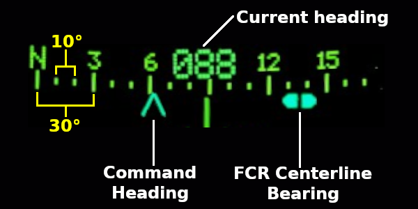
Heading Tape
The Heading tape shows you the current heading of the aircraft, as well as the bearings of items of interest. Currently, the only two implemented are the Command Heading (the next waypoint) and the FCR Centerline Bearing (moves when the FCR is scanning.)
Barometric Altitude
Displays the height of the helicopter with respect to mean sea level. It assumes a standard barometric pressure of 29.92 Hg at all times. This is shown to the top-right of the attitude indicator.
VSI and Radar Altimeter
The VSI, or Vertical Situation Indicator, shows more information about both the aircraft’s vertical speed and radar altitude, on the left and right respectively. Each side has its own scale.
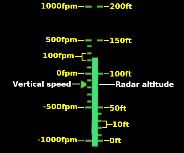
The radar altitude tape is only shown at 200ft AGL and below. Above 200ft, the radar altitude is replaced with the barometric altitude.
Bank Angle and Slip indicator
The bank angle represents the roll of the helicopter to any one side.
The slip indicator represents the adverse yaw of the helicopter when in a turn or in a crosswind. It basically shows how the tail or the nose of helicopter is with respect to a straight and level flight.